| User | Post |
|
3:52 am
October 5, 2010
|
Luke Maurits
| | Adelaide, Australia | |
| Admin
| posts 1471 |
|
|
I'm posting this here because there currently isn't a dedicated part of the forums for PROJECT BALLOON. Once the names are chosen we'll need to do this (assuming we want to stick with the forum system), at which time this can be moved.
I've been doing a little bit of learning about the Arduino boards and their extensions ("shields") as well as how to program these things. I've taken a real shine to Arduino, and in this post I'm going to outline what I think might be an effective and fairly straightforward way to handle the electronics for PROJECT BALLOON.
I'll start with a very quick overview of the Arduino boards and Arduino shields.
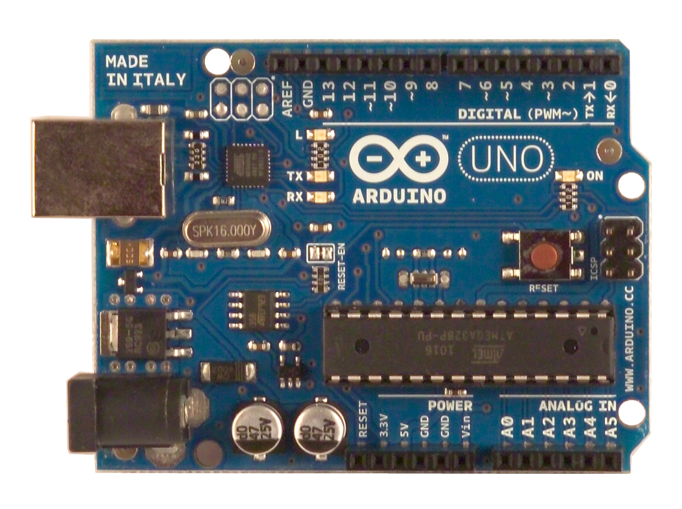
Each Arduino board comes with a fixed number of digital and analogue input/output pins. Here's the current basic Arduino board, the Uno. You can see fairly plainly the 14 digital pins along the top and 6 analogue pins along the bottom.
You can connect whatever you like to these pins in order to do stuff. It's very common in the Arduino world to buy things called "shields" which are extra boards which sit ontop of your Arduino, with pins slotting into the digital and/or analogue pins of the Arduino below it – just like sticking a PCI or AGP card into a motherboard, for instance. Here's a picture of an LCD/keypad shield sitting atop an Arduino board. You can see fairly clearly the connection between the shield and the board's analogue inputs:

Now, typically you attach a single shield to an Arduino to do something, but there's (sometimes) nothing to stop you stacking shields on top of shields, so that you can get monstrosities such as this:

This kind of super stacking will "just work" if the different shields all use different I/O pins on the Arduino board. If multiple shields use the same pins, you need to put some extra layers between them to redirect the pins (and change your software to reflect this). It's inconvenient, but not conceptually difficult or hard to get right.
Now, for PROJECT BALLOON: I've found the following shields at SparkFun:
Based on SparkFun's descriptions of which kind of and how many I/O pins these shields use, I believe it is possible in principle to stack all 3 of these shields onto a single Arduino Uno board. With the right software, this would let us create a fairly small box of electronics which functions like this: you turn it on and it starts reading GPS coordinates; every 10 seconds (or whatever interval we like) it writes a timestamped set of coordinates to a .csv file on the SD card; every 10 minutes (or whatever interval we like) it sends an SMS of the current coordinates to one or more predefined phone numbers. It just sits in this loop until you turn it off or the batteries die. This is, I think, all of the basic navigation and communication features we would need for the very first stage of PROJECT BALLOON. We could attach this box plus whatever payload we like to a balloon and let it go and (unless we are somewhere remote without cellular signal) find it again later.
The total cost for all the components needed to build this (an Arduino Uno board, the 3 shields and a basic GPS module) is about US$225 – not too bad. I also think this approach is pretty compatible with our social contract and design philosophy – the Arduino boards are open source hardware, and we're doing very little actual building ourself by using off-the-shelf shields. The only electronic design which might be involved is re-routing the connections from the shields to the Arduino board to avoid pin conflicts – very simple. We're not designing our own circuits or anything.
With regards to future extension, this stack of shields would, I believe, use only 9 of the Arduino's 14 digital I/O pins, meaning we have 5 left which we could use for temperature/pressure sensors (for instance) or, at later stages of the project, to connect to a non-cellular communication system (something ham radio-ish) and/or to accept arbitrary data from a secondary payload. Note that if we run out of pins we can buy an Arduino Mega for an extra $20 – it has a total of 54 digital pins and 16 analogue pins, which is more than we could ever need.
In addition to the hardware side of things seeming very straightforward – kind of like lego, really – I've had a brief look at the software side, and that seems relatively easy too. I'd volunteer – with confidence – to start building this device myself, learning as I go, and expect to have the basics working in a few months, if I didn't know full well that it would take over my life until it was perfect, which I can't afford right now.
Does anybody have any compelling arguments to not approach PROJECT BALLOON in this way? I know that in the past we have discussed using Smartphones to do this. This could well be cheaper, but for one thing it is less open and for another thing it's probably less extensible, when we come to consider things like input from sensors or the use of non-cellular communications.
If people think this looks like a promising way to go about the project, then, once the project has a name and some clearer requirements/stages, it might be a good idea to make a post on /r/arduino at Reddit (867 subscribers, seems moderately active) asking (i) for people to confirm that this would all really work the way I think it would, and (ii) if anybody is interested in helping design, build and test such a device if we provide some or all of the funding.
|
Main CLLARE workgroups: Mission Planning, Navigation and Guidance. I do maths, physics, C, Python and Java.
|
|
|
9:09 am
October 5, 2010
|
brmj
| | Rochester, New York, United States | |
| Member | posts 402 |
|
|
My thought had been ham radio rather than cellular because there is more you can do with it and it is less dependant on local infrastructure, not to mention more "open". Here is an add-on card that can do AX.25 packet radio. There are probably others, but that is the first I found. It requires an external ham radio transceiver, but there are some handhelds the size of a credit card.
In fact, there is currently an ebay sale for a duel band, mini HT, a full sized 220 HT, and a pair of 2-meter mini HTs, all for around $100. I was looking at buying it anyway for the duel band and 220 handhelds, leaving two that would be ideal for this project. The sale closes in just over a day, and I'm not sure if I intend to purchase them, but if people think it would be worthwhile for the project, I definitely will. Of course, these are low-power radios so communicating with them from the ground may require at least the sort of handheld directional antenna that hams often use for satellite communications. It didn't stop Meteor from using one of theses in their microsatellite design, though.
Actually, now that I think about it those systems might complement each other nicely if we could afford the mass. I doubt cellular works well at high altitudes, but it would really simplify recovery on the ground.
Moving on to other topics, we are going to want some simple instrumentation like to determine altitude, such as a pressure sensor. Other than that, I suspect your list is pretty good for the bare essentials. Thanks for doing that research.
I will volunteer to lead this project. Micro-controllers and radio are fairly well aligned with my interests, ITAR ought not to apply to a high altitude balloon, and I will be able to access the resources of an entire technical school, including our amateur radio club and what is left of Project Meteor.
|
Main work groups: Propulsion (booster), Spacecraft Engineering, Computer Systems, Navigation and Guidance (software)
|
|
|
4:36 pm
October 5, 2010
|
Luke Maurits
| | Adelaide, Australia | |
| Admin
| posts 1471 |
|
|
Thanks a lot for finding that ham shield! I agree that ham is more capable and open than cellular. The only reason I didn't address it much in my post is that I didn't imagine there would be ham shields like the one you found.
I have always thought that the later stages of PROJECT BALLOON should feature both cellular and ham because, as you say, they complement each other well. Ham is much more capable (e.g. if we want to relay arbitrary data from secondary payloads, ham seems to me a much smarter idea than cellular), but cellular is super simple – everybody on the recovery team for a launch is likely to already own a cell phone, and nothing else, like directional antennae, are needed. The learning curve is zero. Using cellular only for the first stage and then adding ham to a later stage makes sense to me, but of course this is up for discussion.
That stuff you are watching on eBay sounds to me like it would be helpful, but I'm not that knowledgable about ham radio yet and I'd hate to encourage you to buy something that you later find to be not useful just because it sounded exciting to me.
With regard to simple instrumentation, I think SparkFun should have us covered there, too. E.g., here's a digital thermometer and digital pressure sensor. They're both fairly cheap and small. They also have small and cheap CMOS cameras which could be handy, too.
It's absolutely fantastic that you're willing to volunteer to lead this project, that will hopefully do a world of good for making sure things keep rolling. Everything Arduino related is free as in freedom and Linux-compatible, too, so you should be able to avoid any moral conflicts. You'll also hopefully have some project Meteor folk to get advice from as well.
|
Main CLLARE workgroups: Mission Planning, Navigation and Guidance. I do maths, physics, C, Python and Java.
|
|
|
5:41 am
October 7, 2010
|
Luke Maurits
| | Adelaide, Australia | |
| Admin
| posts 1471 |
|
|
Post edited 5:56 am – October 7, 2010 by Luke Maurits
I've been doing yet more Arduino reading (what can I say, the things are seriously cool!) and I am now even more confident that the shield stack discussed here can work well.
The GPS and Cellular shield both communicate with the Arduino board over a two-pin digital serial channel – you can just read and write bytes to them like you'd read them from a file descriptor in a C program on your normal computer. Now, the Ardunio Uno comes with some dedicated hardware to handle this kind of data, i.e. a chip that translates the fluctuating voltages on 2 pins into bytes and stores them in a buffer to be read later. This dedicated serial hardware is connected to the 0th and 1st digital I/O pins on the Arduino board, D0 and D1.
Now, there is only one hardware serial channel like this, but the standard Arduino libraries come with a library that lets you set up software serial channels on other pins, i.e. the Arduino board's microprocessor does the same job as the dedicated chip so that you can add additional serial channels (although at the cost of processor time and memory, obviously). By default, the software serial library uses pins D2 and D3.
Both the GPS and Cellular shield are wired to talk to the Arduino board on D0 and D1 by default, but on both shields you can either flip a switch or move a jumper to get them to talk on D2 and D3. This means that we can directly stack these two shields and get them to talk over separate pins. No rewiring required whatsoever. Awesome.
The SD card shield communicates over a different kind of bus, something called SPI. This requires 4 pins instead of 2. Once again, the Arduino board comes with some dedicated hardware for talking over this bus – it uses pins D10, D11, D12 and D3, so there is no conflict with either of our 2 pin serial channels for the GPS and Cellular shields. This means that we can just directly stack this shield again without any rewiring. Awesome.
This leaves pins D4, D5, D6, D7, D8, D9 and D13, and all the analogue pins free for other applications.
Now, let's talk sensors. It seems like most of the sensors on SparkFun's site (things like temperature, pressure, humidity and even some cameras) communicate over yet another bus, this time something called I2C. This requires only 2 pins. Once again, the Arduino board comes with some deciated hardware for talking I2C – even though I2C is a digital protocol, for some reason the Arduino board uses some of its analogue pins, A4 and A5 for this channel. These are the only two I2C pins on the board, and while it's possible to set up more using software (similiar to the serial case), it's not actually necessary. The nice thing about I2C is that it supports multiple devices. You can connect up to around 120 I2C devices in parallel on the A4 and A5 pins and still talk to them individually. This is possible because each I2C device has a unique identifying code on it, called a "slave address" – this is kind of like an ethernet device's MAC address. When reading and writing from the A4 and A5 pins, you just pass the slave address to the function calls as an argument – much like you'd pass a file descriptor to fprintf in C or the like. This means we can put all of our sensors on A4 and A5 and be okay.
So at this point we have GPS, cellular communication, SD data logging and up to 120 sensors all connected to the same board and we still have plenty of pins left – which we could use to run status LEDs, or trigger the deployment of parachutes, etc.
In summary: while I'm still not 100% confident because I'm new to all this, everything which I have read, and felt I understood, suggests that we can totally build the shield stack described in this post without doing any rewiring of our shields and without paying extra for a bigger Arduino Mega board. It all works out, at least from the perspective of pins and buses. It's possible that total power requirements or the Arduino clock speed will prevent this, but I kind of doubt it.
I wish I'd been able to figure all this out back when SparkFun were having their $100 of free stuff sale!
Here are some links to documentation on Arduino libraries for dealing with the kind of buses involved in the stuff described above:
It all seems relatively straightforward. The combination of dedicated hardware chips for protocol work and good software libraries means that communicating between these devices is basically as straightforward as reading and writing to and from files in a "normal" programming language. Brmj, I suspect you would have no difficulty learning this stuff pretty quickly.
If we want to press ahead with this, I see no reason we couldn't start more or less immediately. As a minimal starting package, an Arduino Uno, the SD shield and a digital thermometer would come to US$50 (plus postage). Someone could use that combination to try building something which just logs temperature data to an SD card. Once that goes well we could buy a GPS shield, get logging on that to work, etc., and build our way up as our skills and confidence increases.
|
Main CLLARE workgroups: Mission Planning, Navigation and Guidance. I do maths, physics, C, Python and Java.
|
|
|
1:32 pm
October 7, 2010
|
J. Simmons
| | Dayton, OH, USA | |
| Member | posts 40 |
|
|
Luke,
These are some great links. Ever since you mentioned a balloon project, we've been batting around the idea over here at Mach 30, partly because it is something that has been on our radar for a while (http://mach30.org/forums/mach-…..ce-for-150), and partly because as you have talked about, it just makes for a nice size project to get things going on the hardware front. We also thought flying a High-Altitude Balloon would make a nice centerpiece to an awareness campaign – http://mach30.org/forums/mach-…..e-mid-west.
Funny you should bring up the arduinos. I was just talking to Greg about using them for a High-Altitude Balloon project if we do one of our own. I was looking at some of the projects in the book Practical Arduino Projects for ideas (the vehicle telemetry platform looks promising to me – http://www.practicalarduino.co…..y-platform). I also found this article about another way of using text messaging with Arduino (http://blog.makezine.com/archi….._ardu.html). My thought had been to have the arduino text twitter with status updates so the updates were available on the web (could even format them as links to google maps or something to provide a cheap and easy ground tracking interface).
One more thought Greg and I have had (and I really should cross port this idea to the ODE thread) is to host the balloon design in a redmine install. The idea being that even though it seems unlikely that we will use redmine as the final infrastructure for ODE (rails being a less than ideal framework given our current lack of experience with it and how much broader support there is for php on hosts than rails), we could learn a lot about using ODE from running a nice small project in redmine. Kind of like an uber-wireframe, complete with built-in use case data when the project is done (or partly done). Then we can come back around and implement something in php from scratch (or build on another framework) that incorporates the lessons learned from real use. Best of all, it gets us something to use for now basically right away. I'd throw an install up, except I am in the middle of setting up our new webserver, so it is not quite ready to be put out on the internet.
|
Founder Mach 30, Inc. and Friend of CSTART
|
|
|
2:01 pm
October 7, 2010
|
brmj
| | Rochester, New York, United States | |
| Member | posts 402 |
|
|
Post edited 2:06 pm – October 7, 2010 by brmj
Okay, that's another point in favor of my leading this project. If Mach 30 is going to be doing a project of this sort, it ought to be convenient to have me so close to where J. Simmons lives a substantial portion of the year.
Thanks for all those great links, Luke. I suspect that cmos camera doesn't have the resolution we might want, but other than that everything you posted looks useful. Thank you also for looking into the communications protocols and such involved.
It has come to my attention that we may need a GPS module with special firmware for high altitude use, since ITAR restricts GPS receivers intended for altitudes over 60,000
feet and, as a result, most commercial GPS units self-limit to some altitude under that. Such a receiver can be purchased here, and probably elsewhere.
EDIT: It seems another group doing high altitude balloons has a list of some GPS receivers that ought to work. You can find it here.
Sorry for the short post; I've been busy these last couple of days. I expect to come back and expand upon this in a few hours.
|
Main work groups: Propulsion (booster), Spacecraft Engineering, Computer Systems, Navigation and Guidance (software)
|
|
|
5:13 pm
October 7, 2010
|
Luke Maurits
| | Adelaide, Australia | |
| Admin
| posts 1471 |
|
|
Re: Camera resolution – The CMOS camera I linked to earlier can do 1280 x 1024 resolution at a maximum, I don't know if we'd be satisfied with that or not. Regardless, reading the comments for it on SparkFun it seems like the supposedly excellent manufacturer's documentation is actually inconsistent with how the device actually works, and is also in Engrish, so perhaps we should give it a miss.
Re: GPS maximum altitude – Very good point. The GPS shield linked to above is designed to "just work" with this GPS module, on which someone has commented:
***PUBLIC SERVICE ANNOUNCEMENT: THIS UNIT WILL NOT WORK AT AN ALTITUDE OVER 18000 METERS (60000 FEET)***
This unit uses a Sirf-III GPS chipset has a limitation that buyers
should know about. THIS UNIT WILL NOT WORK AT AN ALTITUDE OVER 18000
METERS (60000 FEET). This doesn't matter to most people, but is
important to hobbyists that take part in high altitude weather
ballooning, amateur rocketry, etc. Someone I know mistakenly purchased a
Sirf-based unit for ballooning and I'm hoping to save people from
making the same mistake.
I'm going to post this in the comments section of all the Sirf-based
Sparkfun products in the hope of saving someone from from making the
same mistake. I apologize if the Sparkfun guys consider this spamming,
that isn't my intent. It, also, isn't my intent to drive business away
from Sparkfun. They have an awesome collection of GPS products and many
of the other modules don't have this limitation.
So that GPS module is a no-go. However, the shield says it is compatible with others, which may not have that limitation. SparkFun's GPS buying guide makes it sound like all the modules work more or less the same way, so it should not be too hard to get a high-altitude GPS module working with the shield. There's a comment on this module which suggests it may be suitable for ballooning.
Re: SMS and Twitter on Arduino – J., that library looks really nice, I was expecting that one of us was going to have to learn the AT command language to get SMS working, but if that can be abstracted away from, all the better. The Twitter messaging idea is a great one, too, that never would have occurred to me. It would be good for publicity, in that even people not on the tracking and recovery team could follow the flight's progress.
Re: Using Redmine – I had been having similar thoughts for CSTART, actually. With our 4 new projects looking likely to have names, logos and project leaders in the near future, now would be an opportune time to "reboot" our web infrastructure too. I don't think forums are super well suited to engineering, and I also worry about WordPress' forum software's scalability to a large set of projects – we will start having forum namespace clashes eventually, I think. Using Redmine as a stand-in for ODE might be a good idea. It would also encourage development of ODE from Redmine. Now that there seem to be a lot more interested people on /r/tothemoon, we may be able to find some Ruby hackers willing to help.
|
Main CLLARE workgroups: Mission Planning, Navigation and Guidance. I do maths, physics, C, Python and Java.
|
|
|
5:33 pm
October 7, 2010
|
Luke Maurits
| | Adelaide, Australia | |
| Admin
| posts 1471 |
|
|
Just read the data sheet for that GPS module above (the Venus634FLPx), to me it seems entirely unambiguous that we should be able to use it. The data sheet claims that the operational limits are altitude < 18000 m and velocity < 515 m/s, and it says that either may be exceeded but not both. The velocity limit is well past the speed of sound, so we won't be exceeding that (at least not on the way up), which means that there is no altitude limit beyond whatever the inherent limit of the GPS infrastructure is.
SparkFun also say "This is the smallest, most powerful, and most versatile GPS receiver we carry", and at $39.95 it is actually cheaper than the larger, altitude-limited module that the GPS shield is designed for. I'll do some more research to find out how easy it would be to get the Venus moduel working on the GPS shield.
|
Main CLLARE workgroups: Mission Planning, Navigation and Guidance. I do maths, physics, C, Python and Java.
|
|
|
6:58 pm
October 7, 2010
|
Luke Maurits
| | Adelaide, Australia | |
| Admin
| posts 1471 |
|
|
Okay, starting to understand things better.
The GPS shield is not designed for that altitude-limited GPS module per se. It is designed for a specific kind of connector cable, the EM 406, which the altitude limited GPS module uses. If you look at the GPS shield, you can see, in the bottom right, a 406 connector. Next to it is a space where you can solder on a 408 connector if you have a GPS module which uses one of those. The idea is, I think, that you just stick the pins of the GPS module into the large pinned area in the middle, and then plug the cable from the module into your 406 or 408 connector. The large pinned area, as you can see, isn't actually connected to everything else.
Now, the Venus module doesn't come with a 406 or 408 connector cable. It comes as just a naked chip that you have to hook up yourself. However, SparkFun do sell this, which is just the Venus module soldered to a tiny board with connections from all the module legs to nice easy to use connectors (this kind of board is called a breakout board). In addition to breaking out the Venus module pins, the board also has an SMC connector for attaching an antenna – the Venus module does not have an onboard antenna like the altitude-limited one linked to above. This is unfortunate in that we have to add the cost of an antenna, but they seem fairly cheap.
Now, back to the GPS shield – note that all the tracks running away from the 406/408 connectors run through some connector points labelled TX and RX (transmit and receive) and 5V and 3.3V (power sources). There are correspondingly marked connectors on the Venus breakout board. I believe if we just ran wires between corresponding connectors, everything should work.
That said, in this configuration the GPS shield is a largely unecessary middle man. Looking at the tracks on the GPS shield, it appears that all that shield does is connect the Arduino board's 5V and 3.3V power pins to the corresponding power pins of the GPS module, passing them through a button and a switch for on/off and reset capabilities, and connects the GPS module's TX and RX pins to the Arduino's hardware serial pins D0 and D1 or, if you flip a switch, to any two other pins (the two little solder blobs marked 2 and 3 next to the hardware/software serial switch are clearly just intended for you to run wires from them to two other digital I/O pins of your choosing). It's really that simple.
Considering that we don't (I think) actually need on/off and reset capabilities for the GPS module independently of our entire avionics box, and that we're not going to want to switch back and forth between hardware and software serial, using the GPS shield is a waste. We can just buy the Venus breakout board and run wires ourselves from the Venus module's 5V, 3.3V, TX and RX pins directly to the corresponding pins on the Arduino board – this is a really simple job, it would just require 4 soldering points on the Venus breakout board, on the Arduino side we wouldn't even need to use solder if we could find some wires which ended in pins that could be inserted into the Arduino's headers.
All of this raises the question of just what all the other pins on GPS modules do if the power pins and serial TX/RX are all you need for basic functionality (I can see one marked "BAT" which is obviously for a backup battery), but I suppose it doesn't matter much.
Note that the cost of a GPS shield and the 406-connected altitude-limited GPS module is US$77. The Venus breakout board costs US$49.95 so unless a few bits of wire and a GPS antenna with an SMC connector cost US$27, this new option is going to be cheaper – and it gets us a better GPS module and probably saves a bit on weight and space, since the Venus breakout board is cheaper than the GPS shield.
|
Main CLLARE workgroups: Mission Planning, Navigation and Guidance. I do maths, physics, C, Python and Java.
|
|
|
7:08 pm
October 7, 2010
|
Luke Maurits
| | Adelaide, Australia | |
| Admin
| posts 1471 |
|
|
Just been looking at the packet radio shield brmj linked to. It, like all the various widgets you can hook up to an Arduino, seems blessedly simple. I honestly can't believe how bloody simple it is to build awesome electronic devices with microprocessor boards. It seems like you can basically just send and receive packet data using the standard two pin serial system, just like reading data from a GPS module. Now, with the radio shield, a GPS module and a cellular module, we are up to 3 serial channels, which means 2 software channels in addition to the Arduino's onboard one. I haven't seen anything which suggests you can't do this, but the Arduino's processor may not be fast enough to run all three serial channels simultaneously at the required speeds. However, since I presume radio will come along in a later stage of our ballooning program, by that stage we will probably need to upgrade to an Arduino Mega anyway, to be able to handle things like I/O with secondary payloads.
|
Main CLLARE workgroups: Mission Planning, Navigation and Guidance. I do maths, physics, C, Python and Java.
|
|
|
1:38 am
October 8, 2010
|
brmj
| | Rochester, New York, United States | |
| Member | posts 402 |
|
|
On the GPS issue: Good job finding one that will work. Too bad about the antenna, but those are cheap and if necessary, easy to make. Here is one such antenna sparkfun offers. I'd like to point out that the GPS module you found uses 3.3 V and arduinos typically seem to use 5 V. This isn't a huge problem, however, as sparkfun sells a little logic level voltage conversion widget for under $2.00. It does add a little complexity, though.
On the GPS shield issue: I agree that the breakout board ought to be almost a drop-in replacement. I suppose the real question is how much time we are willing to spend doing a little extra work to make do with cheaper hardware.
On the "three serial channels" issue: There is no reason at all that that should become a problem, assuming a sane interface for all of those devices and reasonable software design on our part. Think of it this way: How often does one really need to get new GPS coordinates to get a pretty good picture of where a balloon is going? How much time do we want between transmissions of telemetry? Can we not stagger the usage of GPS, cell phone and ham radio such that we aren't using all three, or even just two, at the same time?
I've been reading a lot about arduinos these last few hours, and the more I read, the more excited I get about this approach. I am pretty sure this will meet our needs excellently, and beyond that it ought to be fun to put together.
Also, I thought I'd add that I ended up ordering those radios.
|
Main work groups: Propulsion (booster), Spacecraft Engineering, Computer Systems, Navigation and Guidance (software)
|
|
|
5:12 am
October 8, 2010
|
Luke Maurits
| | Adelaide, Australia | |
| Admin
| posts 1471 |
|
|
Actually, I think most of the Arduinos do both 5V and 3.3V. The Uno certainly does: have a look at the power pins, they're next to the analogue input pins and all labelled. There's a 3.3V and a 5V pin, and a common ground. I read somewhere that on earlier Arduino boards (the ones whose names start with "Deci"), the voltage regulator which produced the 3.3V was kind of flaky and under heavy loads was prone to dropping below 3V, but apparently the Arduino boards have a new, more reliable regulator. So we should be able to power the GPS module from that.
With regards to "how much time we are willing to spend doing a little extra work to make do with cheaper hardware", I think the breakout board is not only cheaper than the GPS shield, but also less work – by the looks of the Venus unit, attaching it to the GPS shield woudln't be easy – it doesn't have pins/legs so much as it just has flat connectors. We'd also have to buy a separate antenna connector, etc.
Regarding three serial channels: while we can certainly stagger the reading and writing to the three serial channels that we do as part of our actual I/O, so that our code is never talking on more than one channel at a time, I think (but could be wrong) that the SoftwareSerial library might still be constantly buffering all the incoming data from the GPS, etc., which will still consume memory and processor time.
Another potential limitation is memory space: the Arduino Uno has 32 KB of flash memory, and we're probably going to use a lot of libraries in this application – most of the data bus libraries plus a FAT fs library, possibly an AT command library. There's a chance all of these libraries together plus our actual application code will exceed 32 KB. I don't really know how compact the libraries are. As with many things, this isn't a huge problem, because upgrading to the Arduino Mega will fix it – that board has 256 KB of memory for code, which really should be ample.
I'm quite excited about all this Arduino stuff too. The power to difficulty ratio seems too good to be true. I'll probably end up buying one myself soon against my better judgement, they just look like too much fun. I'm slowly building a homemade ROV, the prospect of putting an Arduino board in one is basically irresistable.
Regarding the radios that you bought on eBay: how large are the handheld ones, roughly? And is it possible to buy compact boards which do essentially the same thing? I was looking at radio boards on SparkFun today but they all seemed quite low power.
|
Main CLLARE workgroups: Mission Planning, Navigation and Guidance. I do maths, physics, C, Python and Java.
|
|
|
7:07 am
October 8, 2010
|
brmj
| | Rochester, New York, United States | |
| Member | posts 402 |
|
|
Post edited 7:09 am – October 8, 2010 by brmj
Thanks for the correction.
Serial port issue: It may end up being a trivial moification to the library to give it the ability to completely ignore a channel.
Memory: that's something we are going to need to try before we can see if it is a problem.
Radios: the radios are 56x94x11mm and 75 g. There are dedicated boards that do the same thing, but they cost more. On the other hand, with the rest of the package taken into account, these come to something like $20 each. These radios are not exactly the newest out there, but they really do all they need to for our purposses. Project Meteor has the board out of a model that replaced these ones handleing communications in their cubesat. These only produce a 300 mW signal, but there are amatuer radio satalites that transmit on less if I'm not mistaken so I believe this shouldn't be a problem. I was reading elsewhere about ham radio in high altitude balloons, and someone else had been able to communicate to a dedicated radio board transmitting on that much power without dificulty. The line of sight helps a lot.
|
Main work groups: Propulsion (booster), Spacecraft Engineering, Computer Systems, Navigation and Guidance (software)
|
|
|
7:28 am
October 8, 2010
|
antinode
| | |
| Member | posts 64 |
|
|
I've been following this thread and figured I'd give my iinput. For the first stage of the project what you've been talking about should work just fine, though this simplicity does come with increased costs and complexity of a different sort. Don't be afraid of breaking away from prefab Arduino shields. There are many cameras that'd be better suited than that tiny shield camera. Why limit to sending text messages when you could take advantage of a GPRS/3G/4G connection and send live video, photos, and other data? Eventually it'd be nice to see these components consolidated to a single, more compact board. Also, "radio" is ambiguous please be more specific, thanks.
|
|
|
9:39 am
October 8, 2010
|
brmj
| | Rochester, New York, United States | |
| Member | posts 402 |
|
|
I agree with pretty much everything you said above, though I find myself wondering how well any kind of cell phone signal will work that high off the ground. I suppose it depends on the design of the antennas on a typical cell phone tower.
As for custom boards, I have little skill for designing PCBs, but I can etch them and Sparkfun provides eagle files for their boards so it shouldn't be too bad if it becomes neccessary.
The specific radios I was refering to are Alinco DJ-C1T handheld ham radio transcievers. These aren't the newest radios, but they are very small and will meet our needs just fine with the aid of the radio shield. They operate on the two-meter band with 300mW output power. We would be using them with the AX.25 packet radio protocol, which is essentially the standard in the ham radio community for transmitting computer data over radio and is supported in the Linux kernal, making communicating with the system very easy.
|
Main work groups: Propulsion (booster), Spacecraft Engineering, Computer Systems, Navigation and Guidance (software)
|
|
|
6:13 pm
October 8, 2010
|
Luke Maurits
| | Adelaide, Australia | |
| Admin
| posts 1471 |
|
|
While I agree that it would be really nice to have all of this stuff on one custom made board, I have to wonder if it is worth it. The effort involved in acquiring all the components on the Arduino and all its shields individually, having our own board etched and then soldering all those components on is pretty heavy, compared to buying around 5 components from a single supplier and basically lego-snapping them together. I suppose it might save us some money (although I don't know how expensive etching is), but I am not too sure that the amount of money saved would be a fair trade for the hugely increased construction effort. It's not like the Arduino-based system we've discussed here is super expensive. What other benefits would it bring?
A potentially smaller and lighter system seems likely, but again I'm not sure the Arduino-based system would be prohibitively large or heavy. I suppose if nothing else it gives us practice with circuit design and construction which will probably be a lot more necessary for, say, the CubeSat project, which will need a lot of the same kind of electronics onboard and then some, and in that situation space and weight will be at a premium.
With regards to live video over cellular: I really know very little about the technology behind modern phones, so this is a total stab in the dark, but antinode, you mentioned taking advantage of GPRS, and the SparkFun page for the cellular shield says "This allows you to easily add SMS, GSM/GPRS, and TCP/IP functionalities to your Arduino-based project" (emphasis mine), so what you suggest might indeed be possible.
I wonder if we should have camera capabilities at all on the main unit, or just dedicate the main unit entirely to tracking, comms and data-logging, with the idea being that we can hang arbitrary units off the main unit depending on purpose, and then maybe develop a really awesome camera unit, perhaps with one really good camera facing in some direction but at least small CMOS ones on every face so we get a decent all around view? Probably a bit premature to think about this, once we have a project name and designated leader(s) we can get to work on really outlining the overall architecture.
|
Main CLLARE workgroups: Mission Planning, Navigation and Guidance. I do maths, physics, C, Python and Java.
|
|
|
11:30 am
October 9, 2010
|
brmj
| | Rochester, New York, United States | |
| Member | posts 402 |
|
|
As I type this, I am sitting in the local ham radio club room. Several club members more experienced with such things than I am confirm that attaching the GPS chip to our system ought to be as simple as we thought, or perhaps even simpler. Also, they seem to basically agree with me on the radio issue and the suitability of the HTs I found for that purpose. Several club members are expressing interest in the project. I am feeling more and more optimistic about this as time goes on.
|
Main work groups: Propulsion (booster), Spacecraft Engineering, Computer Systems, Navigation and Guidance (software)
|
|
|
5:13 am
November 29, 2010
|
rpulkrabek
| | |
| Member | posts 309 |
|
|
I'm not so much an expert on circuit boards. I did, however, stumble across a post describing a similar board to arduino. Perhaps this deserves a look, but, like I said, I'm not an expert :)
http://www.engadget.com/2010/1…../#comments
|
|